
DEMO - Fabricator: From BIM export to automated welding and fitting
Watch the demo video or continue reading to learn how to move from BIM detailing to automated welding and fitting using LogicSteel CAD/CAM and the Fabricator.
STEP 1: Prepare the BIM model
Detail your steel structure in a supported BIM environment. For example, Tekla Structures or SDS2.
At this stage, you work as you normally would. Define parts, assemblies, materials, and welds.
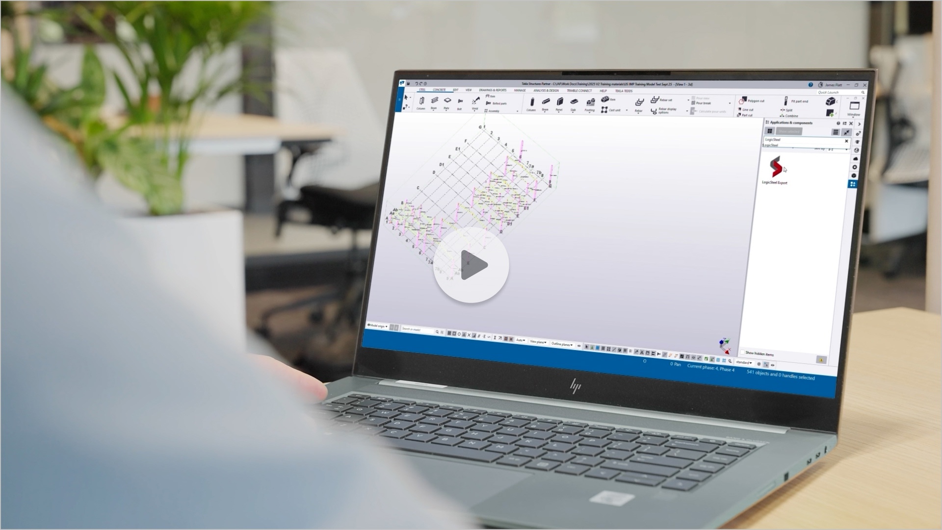
STEP 2: Export the model to the LogicSteel Cloud
When your model is ready, export it directly from your BIM software.
- Open the LogicSteel extension panel
- Click Export
That’s it.
With these two clicks, your BIM model is securely sent to LogicSteel CAD/CAM. No manual file preparation. No file conversion.
After a few seconds, an Upload Report appears.
It shows how many assemblies and parts will be uploaded.
You can:
- download the log, or
- click Continue upload to complete the export
What happens automatically during export
While the export is running, LogicSteel does the work for you.
Automatic doability check
LogicSteel checks every part and assembly against the capabilities of the Fabricator.
It uses all available model data, such as:
- dimensions
- materials
- weld types
- assembly structure
Based on this, the software determines what can be automated and what cannot.
Automatic model validation and correction
At the same time, LogicSteel also checks the model for fabrication issues, such as:
- incomplete welds
- overlapping welds
- clashing welds
- missing weld definitions
These issues are corrected automatically where possible. This ensures the model is ready for fabrication before it reaches the shop floor.
No user action is required during this.
STEP 3: Review the doability overview
After export, LogicSteel CAD/CAM presents a clear doability overview.
Each part or assembly is classified as:
- Fully doable: Can be welded and fitted entirely by the Fabricator
- Partially doable: Suitable for automation, except for specific welds or operations
- Not doable: Outside the Fabricator’s automation scope
For partially doable assemblies, CAD/CAM clearly shows:
- which welds, or
- which operations
cannot be performed automatically.
This gives you instant insight into how your project will be produced. It allows you to spend time on optimizing your welding time.
STEP 4: Plan automated and manual work
Use the doability overview to plan production.
You can:
- assign fully doable assemblies to the Fabricator
- schedule non doable welds for manual welding
- combine automated and manual work where needed
This creates a hybrid workflow. Automation handles repetitive and standardized work. Skilled welders focus on complex connections.
STEP 5: Send assemblies to the Fabricator
Assemblies marked as (partially) doable can now be sent to the Fabricator.
- Download the Fabricator XML
- Open the project, phase, and assemblies
- Click Export > Machine
The files are sent directly to the Fabricator. No additional programming is required.
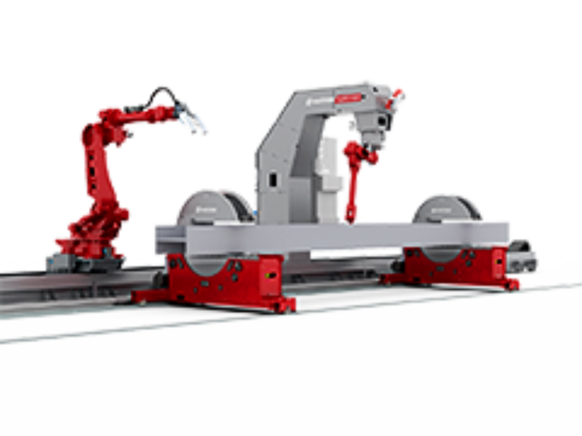
STEP 6: Watch the Fabricator go to work
The operator works from the operator panel. The panel:
- shows which assemblies to process
- helps create cycle lists
- guides the operator step by step
It tells the operator:
- how to position the rotators
- which beam to place in the rotators
- how to set the vertical clamps
Once clamped, the operator places the first sub parts on the part feed table.
From this point on, the Fabricator takes over.
The Fabricator automatically:
- positions the parts
- fits the components
- performs the welding

REFERENCES & RESOURCES
Automated fitting and welding.
LogicSteel CADCAM for welding >>
Automate the entire weld‑preparation process.