 GET QUOTE
 NEWSLETTER
 LOGIN
LOGIN

THE STEP-BY-STEP PROCESS BEHIND AUTOMATED FITTING AND WELDING - From individual parts to finished assembly
BY TJAARD BUREMA,
PRODUCT MANAGER AT VOORTMAN
PUBLISHED: AUGUST 3, 2026
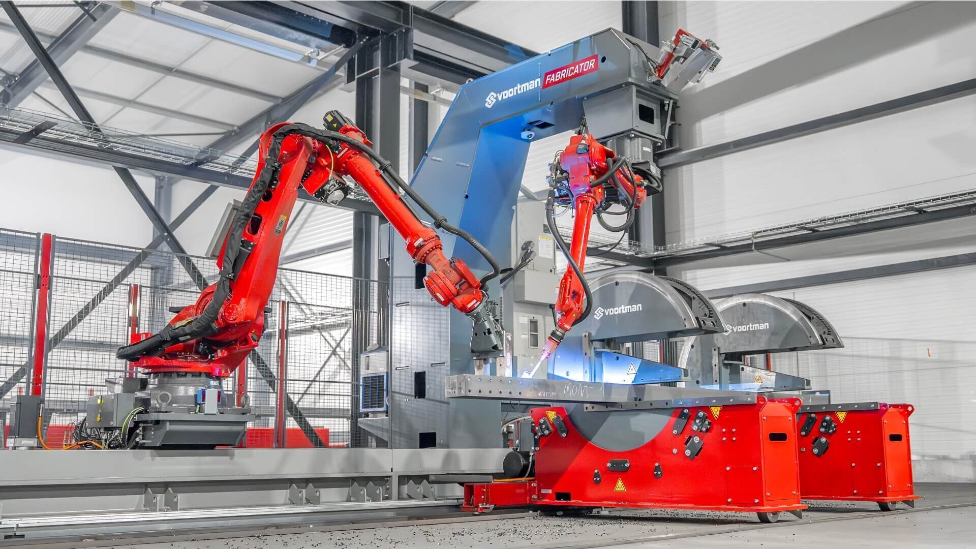
Many steel fabricators explore automation to increase productivity and address labor shortages. But what does automated fitting and welding actually involve?
In this article, we'll walk through the process, from start to finish, with the Fabricator; an automated fitting and welding solution that optimizes your shop performance.
Similar process, automated execution
Many steel fabricators still rely on manual fitting and welding. Automated fitting and welding follows the same process but uses software, sensors, and robotics to perform (repetitive) tasks automatically with minimal human intervention. Automatic positioners and robots work together to align steel parts on a profile during the fit-up process, followed by welding to join the components.
The process can be divided into two phases: work preparation and automated fitting & welding on the machine. Continue reading about the step-by-step process or watch the demo.
Phase 1: work preparation
LogicSteel CADCAM for Weld seamlessly converts CAD models into production-ready CAM weld data through a fully automated work preparation process. By eliminating manual programming, it makes the weld work preparation simple and accessible for every user. This is how it works:
Step 1.1: Prepare the 3D model
Prepare the 3D model for the steel structure you want to create, using your preferred choice of software; Tekla or SDS2.
Step 1.2: Create a project
Create a project in the LogicSteel software suite. Then upload the CAD model to the project in just two clicks using LogicSteel CADCAM. You can add or edit a model at any time, and the software will automatically update the data.
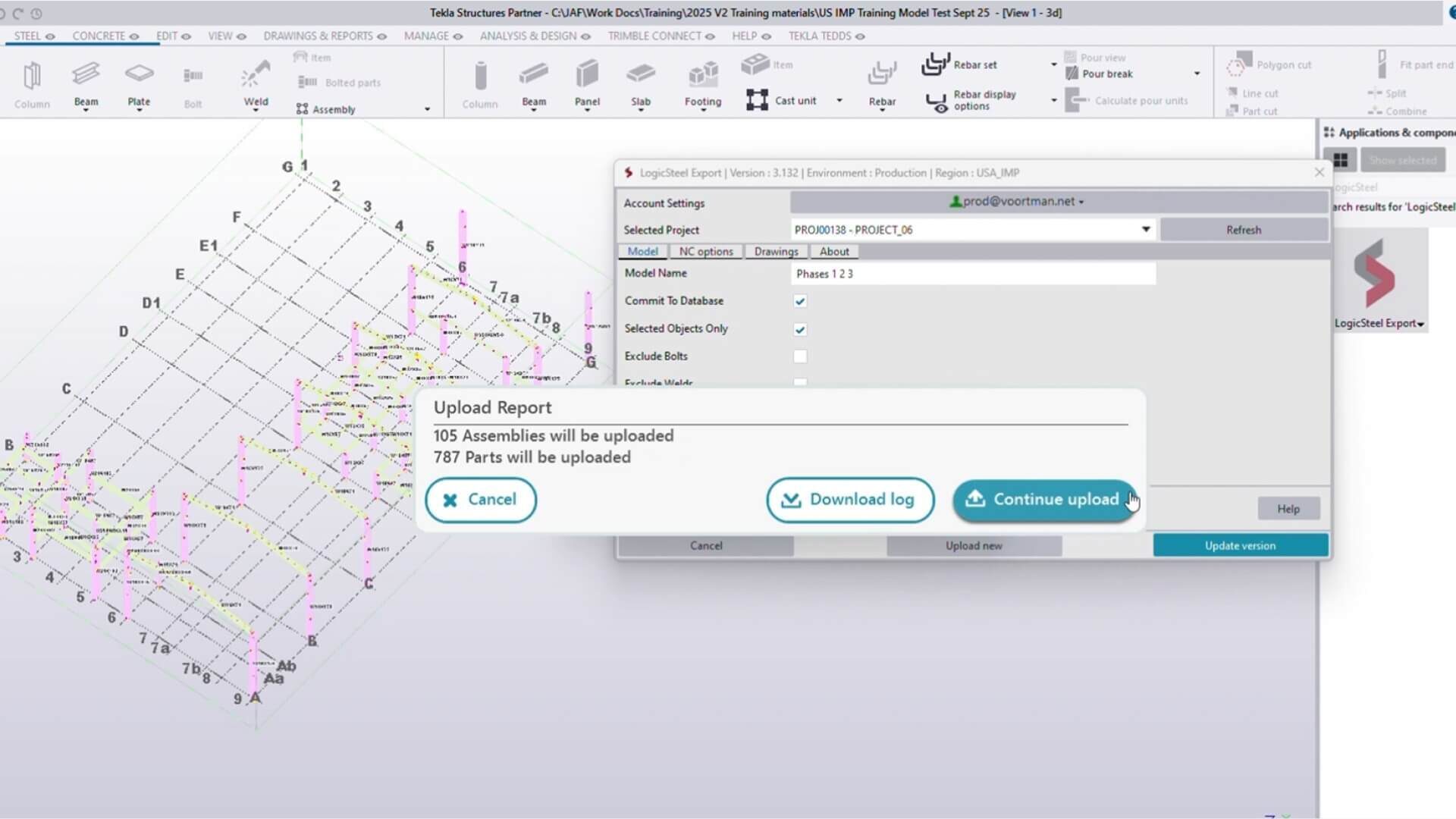
Step 1.3: Automatic check and fix
During the upload, the software runs a check and fix. It assesses if all parts meet material and dimension tolerances, aligns them automatically, and validates all weld data making a quality check redundant. Potential issues like incomplete or missing welds are resolved without human intervention.
Step 1.4: Automatic Doability & Feasibility check
LogicSteel CADCAM then provides insights on estimated production times, performs a doability check to see which assemblies could (partially) and runs a feasibility check as to which assemblies should be welded robotically. Especially, assemblies with many parts attached to the main profile are ideal candidates for the Fabricator, since the complete assembly only needs to be loaded and unloaded once.
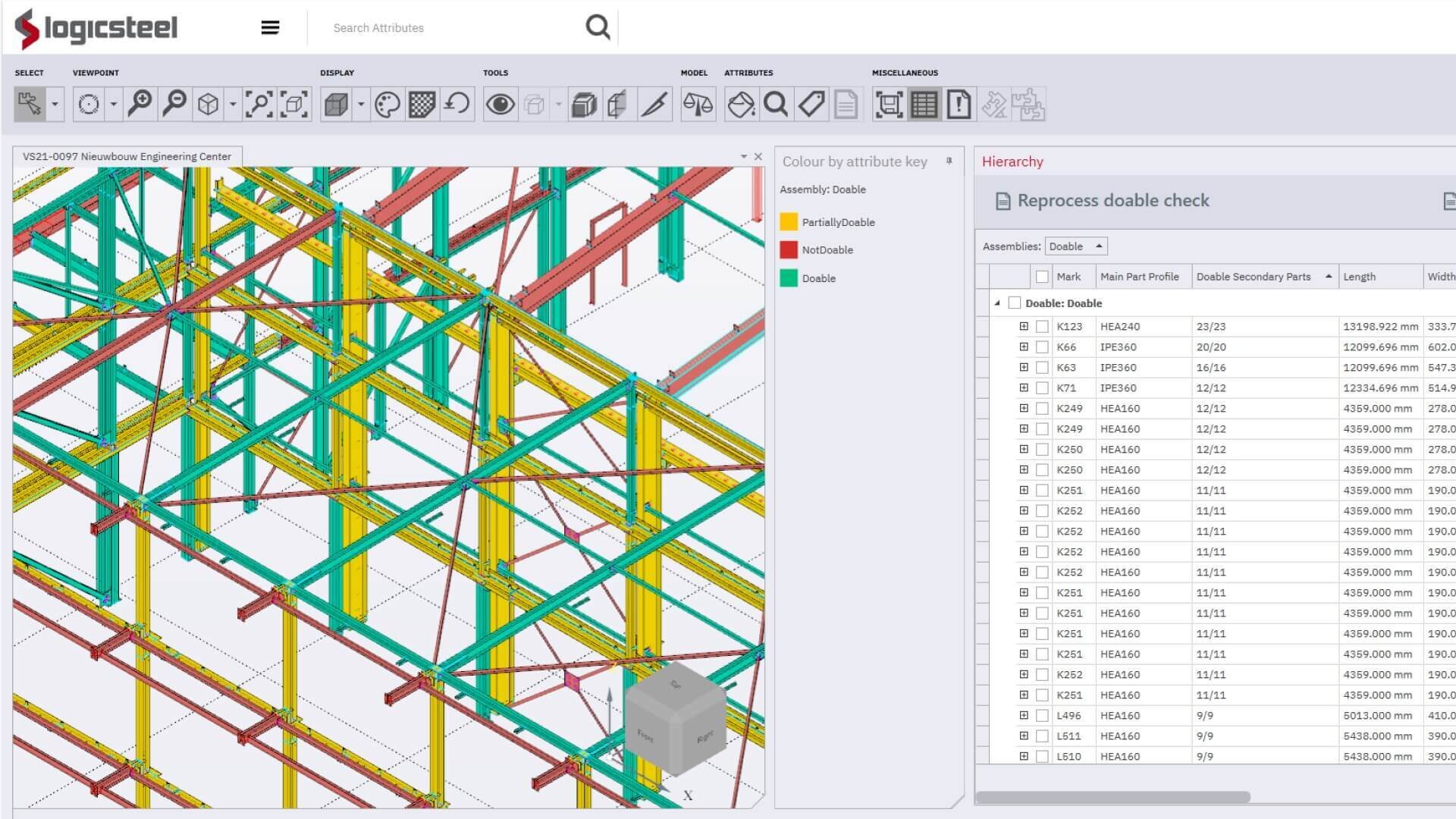
Step 1.5: Review the data
The data shows you the production time estimates of the work when done by the machine versus when processed manually. These insights enable you to optimize your process and achieve most efficiency generating maximum return.
Step 1.6: Select the assemblies to fit and weld automatically
Simply select the assemblies you want to process with the Fabricator. Review the estimated automated welding time and any required manual post-processing for partially weldable assemblies. Determine whether they fit within the available shifts. Once you're satisfied, click export to automatically generate and transfer the CAM data to the machine. No additional programming is required.
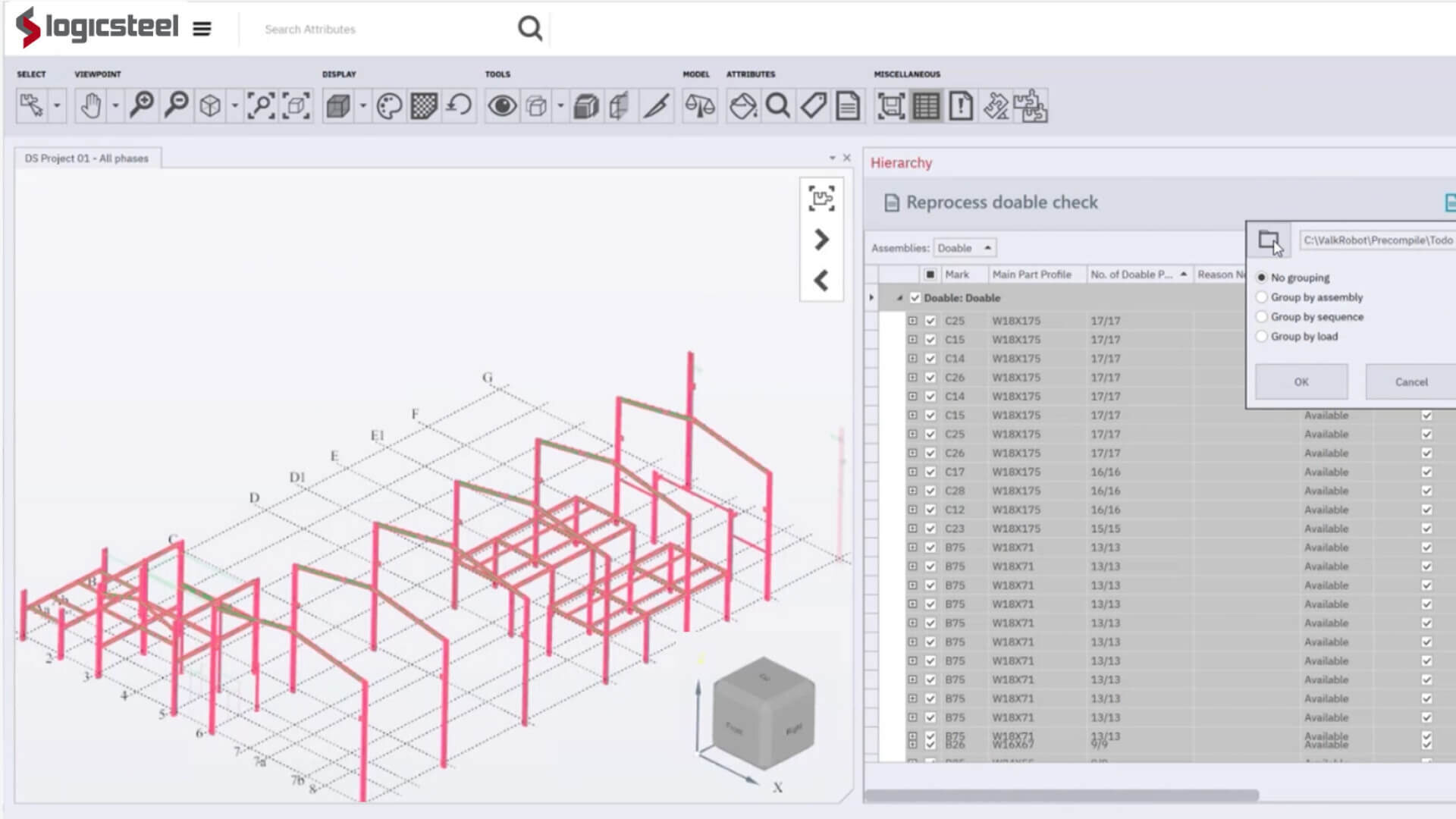
Automated production provides much more detailed production data that is also available in real time. This data can be used to improve progress monitoring and predictability, thereby enabling better planning of welding production. In addition, the Fabricator can significantly improve the logistical process and working conditions, particularly by processing heavier beams and parts to be welded on the machine.
Did you know? Only 2–3 hours of work preparation in LogicSteel CADCAM for Weld can generate enough production data to keep the Fabricator operating for an entire 40-hour work week. On average, each assembly requires just 2 minutes of preparation time.
Phase 2: fitting and welding on the machine
As LogicSteel CADCAM delivers complete, production-ready instructions, operators can start the machine immediately.
Step 2.1: Selection
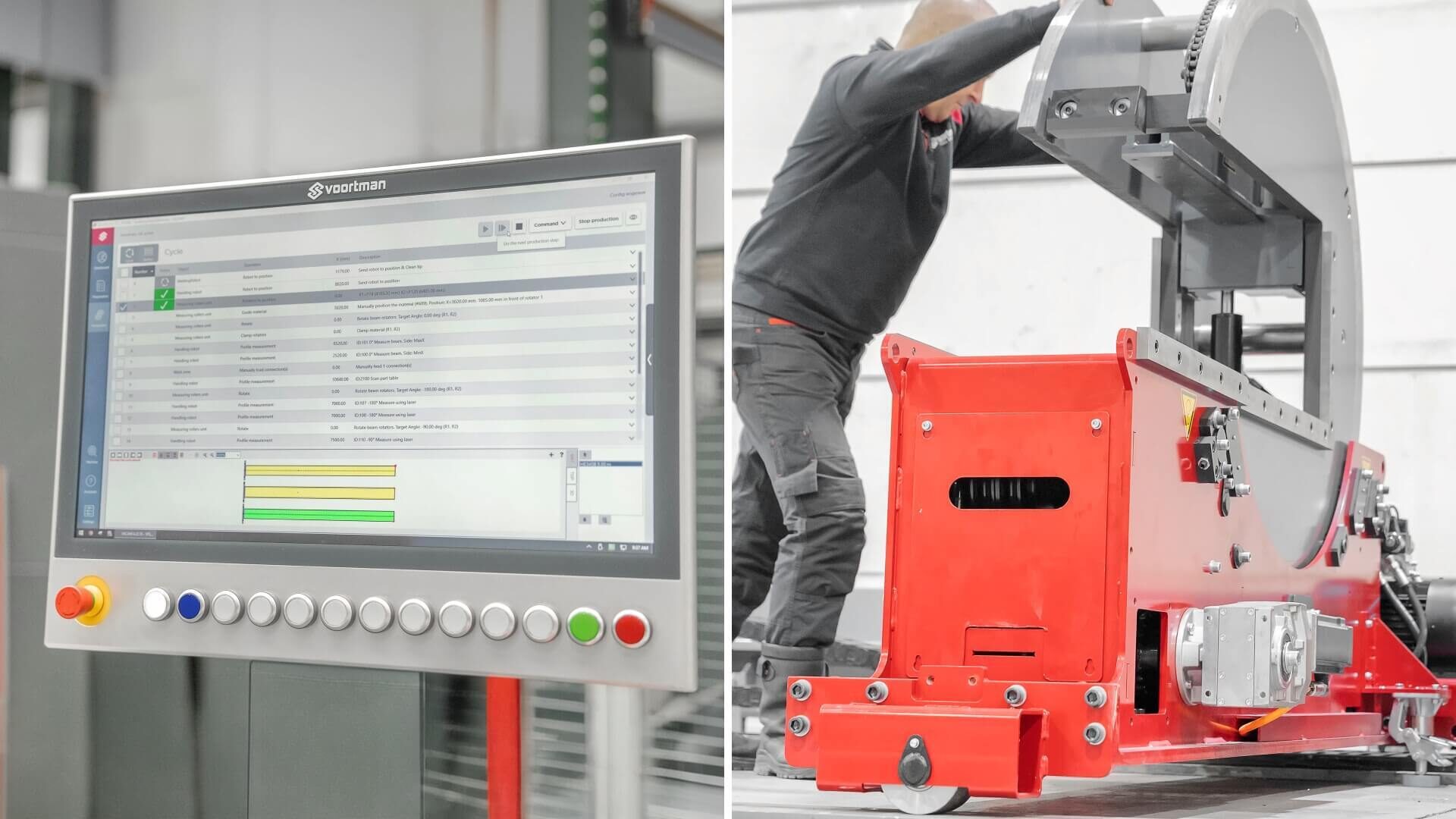
The operator panel at the machine shows which assemblies to process, helps create production lists and provides step-by-step instructions. Select the assembly you want to process and press the green button to start. The machine prepares itself by automatically cleaning the torch.
Step 2.2: Preparation
The settings are displayed on the control panel. The operator positions the rotators using the position markers on the floor. Next, the vertical clamps are adjusted to fit the profile. Load the profile (of at least 26.3 ft/8 m) into the machine. Place the sub parts on the part feed table. Press start and the machine does all the work.
Step 2.3: Final check
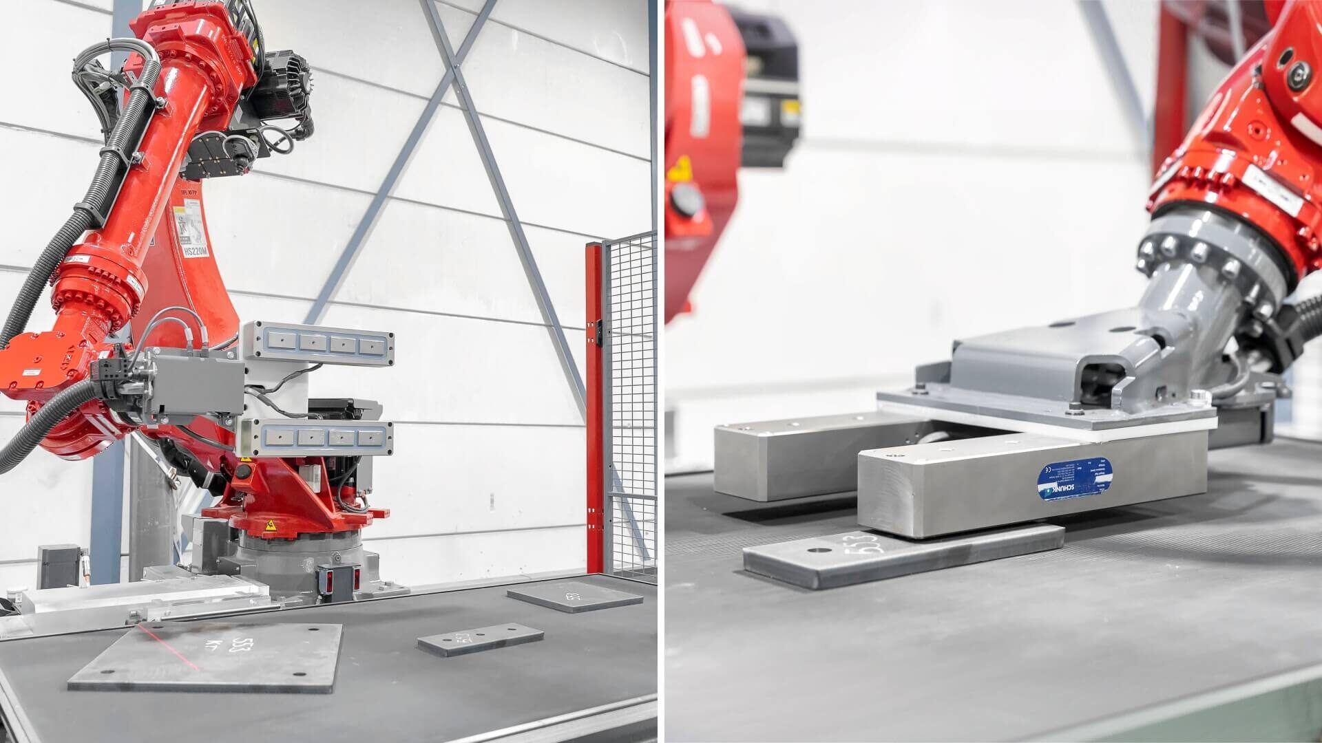
The handling robot locates the outer edges of the part feed table and uses laser scanners and cameras to determine the position of every part. It measures each component to verify that the correct parts, plate thicknesses, and hole locations are present. The collected data is then compared with the imported CAD model and programmed parameters to identify any deviations. Because measurement and fitting are performed automatically, manual layout marking is no longer required.
Step 2.4: Automated fitting.
The system clamps the profile and the handling robot aligns the parts according to the digital model. The clamps can rotate the beam 90 degrees within only two seconds. Parts are automatically aligned using hole-based positioning and laser scanning, ensuring precise fit-up and consistent robotic weld quality. The Fabricator enables parallel processing with multi‑zone operation, which is ideal for large, multi-component assemblies.
The machine automatically handles deviations within predefined parameters. When intervention is required, it alerts the operator while continuing other tasks to avoid downtime.
Step 2.5: Automated welding
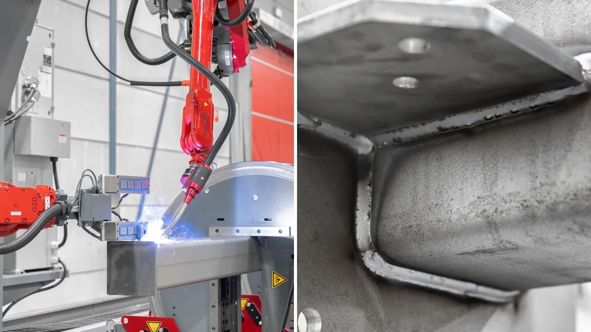
After alignment is confirmed, the welding robot performs the welds following the optimal sequence. The machine calculates whether it is more efficient to first secure everything with a tack weld or to fully weld each part before moving on to the next one.
Step 2.6: Quality checks
The result is a (partially) finished assembly that is ready for a quality check or to proceed to a manual welding station for post-processing the parts the robot could not reach. The operator will receive a digital report of the process when finished.
Did you know? The Fabricator can fit 30 parts per hour and weld about 10 parts per hour. The machine is designed for optimal production time. After all, time is money.
How automated differs from manual fitting and welding
Unlike manual fitting and welding, which requires repeated measuring, positioning, handling, and welding, the Fabricator performs these steps in one continuous process based on a digital model, minimizing manual handling and rework.
Because the system can use all data and measurements in one integrated process, it can reduce errors, improve consistency, and significantly increase productivity, with reported fabrication time savings between 68–78% for suitable steel assemblies.
Interested in automated fitting and welding for your shop?
Are you considering automating your fitting and welding process to increase productivity and address labor shortages?
